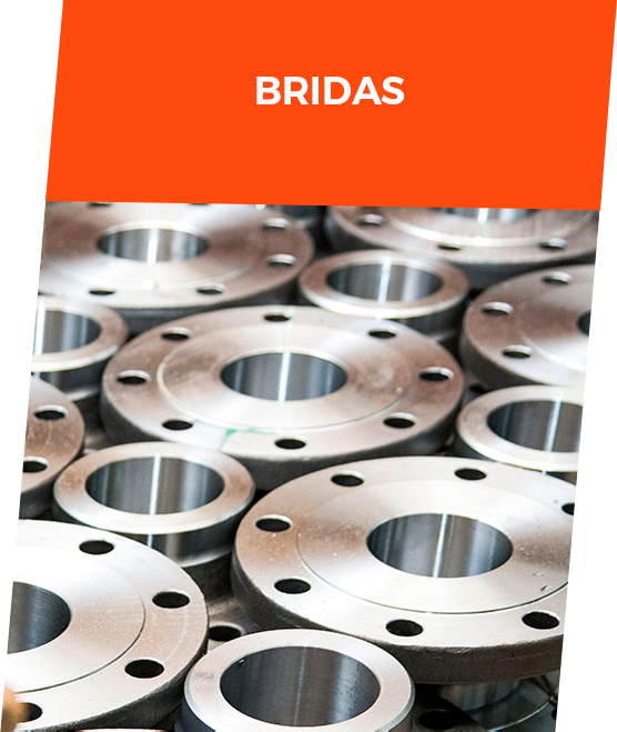
TYPES OF FLANGES
The most common flange designs are:
|API 6A and 6B flanges
|Neck flanges (Welding.neck)
|Crazy flanges (lap joints)
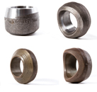
|Socket Welding (Socket Welding)
|Threaded flanges
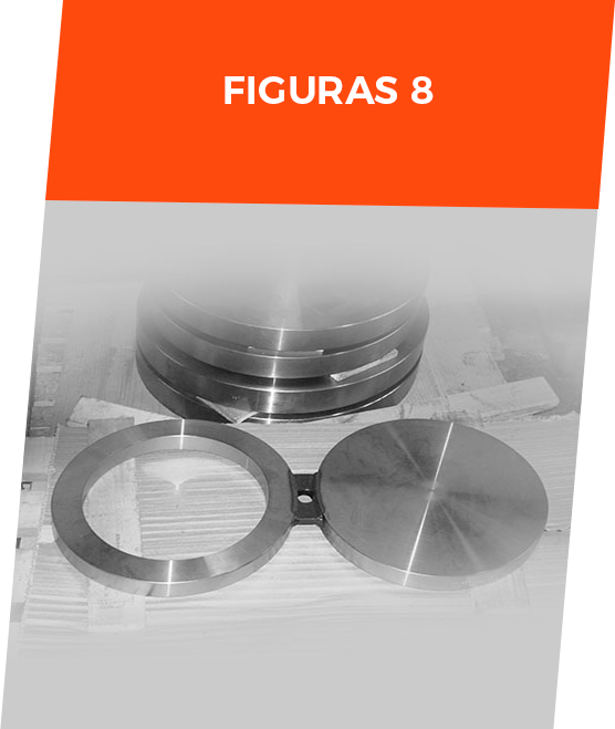
|Blind flanges
|Slip-on cable ties
|Long flanges – welding
|Anchor Flanges
|Double spreader flanges
|AWWA Flanges
FACE TYPES
Flange faces are manufactured as standard to maintain specific dimensions. The most common standard flange faces are:
|Flat face (FF) flat face
|Raised face (RF) raised face
|Face with ring (RTJ)
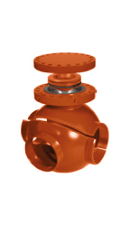
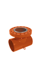
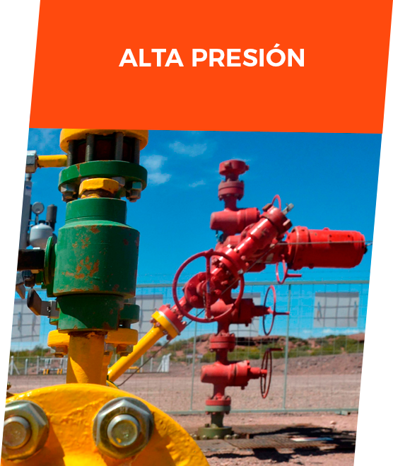
API 6A AND 6B FLANGES
API Specification 6A (ISO 10423) is the recognized standard in the petroleum industry that applies to wellheads and Christmas trees and was created to provide a safe, dimensionally and functionally interchangeable medium.
It provides detailed requirements for the manufacture of equipment for the suspension of tubulars, valves and connectors used at oil and gas well locations which contain and control the pressure and flow of fluid. It also serves as a reference source for the design of flanged connections.
ASME/ANSI FLANGES
Pipe flanges according to ASME/ANSI B16.5 or ASME/ANSI B16.47 are normally made from forgings with machined faces. They are classified according to their “pressure class” (a ratio from which a curve can be obtained according to the resistance to the joint pressure-temperature effect). Pressure classes are expressed in pounds per square inch (abbreviated as psi or simply the symbol #).
The most common pressure classes are 150#, 300#, 600#, 900#, 1500# and 2500#, although ASME B16.47 recognizes class 75# which is intended for low working pressures and temperatures.
The higher the pressure class of the flanges of a piping network, the greater the resistance of the network to the combined effect of pressure and temperature. Thus, for example, a system with a 150# class would hardly withstand pressure and temperature conditions of 30 bar and 150 °C, whereas a 300# class would be ideal for those conditions. The higher the pipe class of a flange, the higher the price, so it would be an unjustified expense to use 600# flanges for this particular case.
OTHER STANDARDS
There are also flanges under the European DIN Standard, which use the designation PN (Nominal Pressure). They are thus classified as PN6, PN10, PN16, PN25, PN40, PN40, PN100, PN250, PN400 BARS. Sometimes the letters “ND” from the German “NENNDRUCK” are still used instead of PN.
MATERIALS
The materials normally used are (according to ASME designation):
|SA-A105
|SA-A266
|SA-A182
|SA-A694