FLANGES
These are elements that allow the connection or assembly of parts, whether pipes, valves, pumps, or other equipment that form part of the line or duct.
TYPES OF FLANGES
|Welding.neck
|Blind
|Ciega
|Socket Welding
|Threaded
|Lap-Joint
|Plate holder
MANUFACTURING STANDARD
|B16.5 (up to and including 24″)
|B16.47 Type A/B (26″ and above)
|B16.36 (Lap-joint)
FACE TYPES
|Flat face (FF)
|Raised face (RF)
|Ring face (RTJ)
SERIES / CLASS
150#, 300#, 600#, 900#, 1500# y 2500#
MATERIALS
|Carbon steel:
· ASTM A105
· A350 LF2 CL1
· ASTM A694 F42 /46/52/56/60/65/70
|Alloy steel:
|Stainless steel:
All our flanges are delivered with their corresponding quality certificate.
TIPOS DE BRIDAS
|Welding.neck
|Slip-on
|Ciega
|Socket Welding
|Roscada
|Lap-Joint
|Portaplaca
NORMA DE FABRICACIÓN
|B16.5 (hasta 24” inclusive)
|B16.47 Tipo A/ B (de 26” en adelante)
|B16.36 (Portaplaca)
TIPOS DE CARAS
|Cara plana (FF) flat face
|Cara con resalte (RF) raised face
|Cara con anillo (RTJ)
SERIE / CLASE
150#, 300#, 600#, 900#, 1500# y 2500#
MATERIALES
|Acero al carbono:
· ASTM A105
· A350 LF2 CL1
· ASTM A694 F42 /46/52/56/60/65/70
|Acero aleado:
|Acero Inoxidable:
Todas nuestras bridas se entregan con su certificado de calidad correspondiente.
DESCARGA DE ARCHIVOS
FLANGES
Flange is the element that joins two components of a piping system, allowing to be disassembled without destructive operations, thanks to a circumference of holes through which union bolts are mounted. The flanges are those elements of the pipeline, intended to allow the union of the parts that make up this installation, whether pipes, valves, pumps or other equipment that is part of these facilities.
The flange is an element that can be supplied as a separate part or can be factory assembled to an element for its installation, whether it is a valve or a pipe, etc. There is a diversity of designs, dimensions, materials and manufacturing standards.
TYPES OF FLANGES
The most common flange designs are:
|API 6A and 6B flanges
|Neck flanges (Welding.neck)
|Crazy flanges (lap joints)
|Socket Welding (Socket Welding)
|Threaded flanges
|Blind flanges
|Slip-on cable ties
|Long flanges – welding
|Anchor Flanges
|Double spreader flanges
|AWWA Flanges
FACE TYPES
Flange faces are manufactured as standard to maintain specific dimensions. The most common standard flange faces are:
|Flat face (FF) flat face
|Raised face (RF) raised face
|Face with ring (RTJ)
API 6A AND 6B FLANGES
API Specification 6A (ISO 10423) is the recognized standard in the petroleum industry that applies to wellheads and Christmas trees and was created to provide a safe, dimensionally and functionally interchangeable medium.
It provides detailed requirements for the manufacture of equipment for the suspension of tubulars, valves and connectors used at oil and gas well locations which contain and control the pressure and flow of fluid. It also serves as a reference source for the design of flanged connections.
ASME/ANSI FLANGES
Pipe flanges according to ASME/ANSI B16.5 or ASME/ANSI B16.47 are normally made from forgings with machined faces. They are classified according to their “pressure class” (a ratio from which a curve can be obtained according to the resistance to the joint pressure-temperature effect). Pressure classes are expressed in pounds per square inch (abbreviated as psi or simply the symbol #).
The most common pressure classes are 150#, 300#, 600#, 900#, 1500# and 2500#, although ASME B16.47 recognizes class 75# which is intended for low working pressures and temperatures.
The higher the pressure class of the flanges of a piping network, the greater the resistance of the network to the combined effect of pressure and temperature. Thus, for example, a system with a 150# class would hardly withstand pressure and temperature conditions of 30 bar and 150 °C, whereas a 300# class would be ideal for those conditions. The higher the pipe class of a flange, the higher the price, so it would be an unjustified expense to use 600# flanges for this particular case.
OTHER STANDARDS
There are also flanges under the European DIN Standard, which use the designation PN (Nominal Pressure). They are thus classified as PN6, PN10, PN16, PN25, PN40, PN40, PN100, PN250, PN400 BARS. Sometimes the letters “ND” from the German “NENNDRUCK” are still used instead of PN.
MATERIALS
The materials normally used are (according to ASME designation):
|SA-A105
|SA-A266
|SA-A182
|SA-A694
DESCARGA DE ARCHIVOS
QUICK CLOSING LIDS
The quick opening and closing lids are an indispensable device for the proper operation and maintenance of Filters, Two-phase / Three-phase Separators, Scrapers Launchers and Receivers, Boilers, etc. They present a functional, modern and economical solution for vessels under pressure, which require frequent and quick access. They can be supplied for Horizontal or Vertical position equipment. They allow a fast access thanks to their opening system by means of hinges or “clamps” that can be operated by a single person without the use of special tools.
Their main benefit is the saving of resources, both in terms of personnel and time spent in the field. That is to say, a Futura Quick Closing Lid gives to the operation of pig entry or filter cleaning, a speed and security of work really differential compared to its counterpart of disassembly and assembly that must be done in front of a blind flange.
The versatility in its varied design, which in all cases can be adjusted to the needs of the available place or the design of the equipment and its constructive capabilities, provide the user with a unique working response.
Available from 3″ upwards and for different working pressure requirements. Just fill in the Data Certification corresponding to the chosen Cover.
Futura Quick Action Caps are always supplied with a User and Installation Manual and our Technical Support to provide you with complete support.
More than 6000 units installed, both in Argentina and Latin America, with no claims of use and operation over time, endorse our product.
HORIZONTAL MODEL | SIDE OPENING
HIGH SPEED AND SIMPLICITY
A simple and very effective solution for small diameter caps. Very fast opening, its system allows it to be used in horizontal or vertical position indistinctly.

OPENING SEQUENCE

HORIZONTAL MODEL | LEVER OPENING
SPEED, SOLIDITY AND STRENGTH
We created a fast system based on the simplicity of its opening system. In a few minutes the operation is performed by one person without the use of special tools. This design is used for medium size lids.
The system of levers and hinges makes it sturdy and safe to operate. The bolts and pins of its closing system are made of stainless steel to avoid galling during opening over time.

OPENING SEQUENCE

HORIZONTAL MODEL | OPENING WITH HANDWHEEL
ROBUSTNESS AND SAFETY
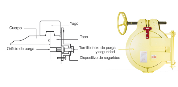
This design is used on large diameter lids. Its operation is very simple, with its safety system on the front of the cover and its operating handwheel, which makes the use of additional tools unnecessary.
OPENING SEQUENCE

HORIZONTAL MODEL | RING LOCK
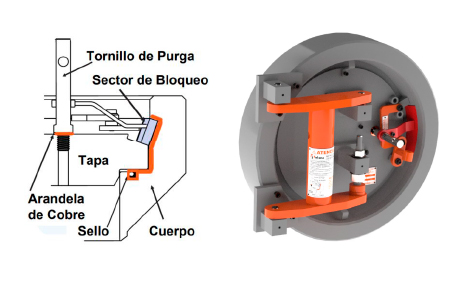
Our Quick-Lock Caps have 10 years of warranty and quality assured because they are calculated according to ASME VIII and validated through finite element calculations and other studies such as the measurement of deformation in the main components. In addition, we have been manufacturing covers for 20 years and they are installed in different countries: Colombia, Ecuador, Peru, Bolivia, Brazil, Uruguay, Chile and Argentina.
OPENING SEQUENCE

FILE DOWNLOADS
DATA CERTIFICATION
FORGING ACCESSORIES
Futura’s plant in Gualeguaychú has the capacity to forge parts to meet the needs of third parties, designing and developing all the necessary tools, including crankshafts, connecting rods, wellheads, spheres and valve bodies, bridge crane wheels, tubular plates, and other parts for companies in the gas, oil, and mining industries.
For this task, we have independent hammer and press lines, both with their own heating furnaces, main machine, and finishing machine (deburring press).
We offer this service on our 4,000-ton press line and 16,000- and 25,000-kg hammer lines to cover parts from 6 to 480 kg.
 high pressure in
  Título de la pestaña 1
  Título de la pestaña 1
  Título de la pestaña 1
  Título de la pestaña 1
  Título de la pestaña 1
 HIGH PRESSURE API
HEADERS AND ARMATURES
CASING PIPE HEADS
CASING PIPE REELS
CASING HANGERS
WEAR BUSHINGS – REMOVAL TOOL
SECONDARY PACKINGS
SINGLE PRODUCTION REELS AND HANGERS
DUAL PRODUCTION REELS AND HANGERS
FLOW CONTROLLERS AND REGULATORS
FLANGES
These are elements that allow the connection or assembly of parts, whether pipes, valves, pumps, or other equipment that form part of the line or duct.
TYPES OF FLANGES
|Welding.neck
|Blind
|Ciega
|Socket Welding
|Threaded
|Lap-Joint
|Plate holder
MANUFACTURING STANDARD
|B16.5 (up to and including 24″)
|B16.47 Type A/B (26″ and above)
|B16.36 (Lap-joint)
FACE TYPES
|Flat face (FF)
|Raised face (RF)
|Ring face (RTJ)
SERIES / CLASS
150#, 300#, 600#, 900#, 1500# y 2500#
MATERIALS
|Carbon steel:
· ASTM A105
· A350 LF2 CL1
· ASTM A694 F42 /46/52/56/60/65/70
|Alloy steel:
|Stainless steel:
All our flanges are delivered with their corresponding quality certificate.
TIPOS DE BRIDAS
|Welding.neck
|Slip-on
|Ciega
|Socket Welding
|Roscada
|Lap-Joint
|Portaplaca
NORMA DE FABRICACIÓN
|B16.5 (hasta 24” inclusive)
|B16.47 Tipo A/ B (de 26” en adelante)
|B16.36 (Portaplaca)
TIPOS DE CARAS
|Cara plana (FF) flat face
|Cara con resalte (RF) raised face
|Cara con anillo (RTJ)
SERIE / CLASE
150#, 300#, 600#, 900#, 1500# y 2500#
MATERIALES
|Acero al carbono:
· ASTM A105
· A350 LF2 CL1
· ASTM A694 F42 /46/52/56/60/65/70
|Acero aleado:
|Acero Inoxidable:
Todas nuestras bridas se entregan con su certificado de calidad correspondiente.
DESCARGA DE ARCHIVOS
FLANGES
Flange is the element that joins two components of a piping system, allowing to be disassembled without destructive operations, thanks to a circumference of holes through which union bolts are mounted. The flanges are those elements of the pipeline, intended to allow the union of the parts that make up this installation, whether pipes, valves, pumps or other equipment that is part of these facilities.
The flange is an element that can be supplied as a separate part or can be factory assembled to an element for its installation, whether it is a valve or a pipe, etc. There is a diversity of designs, dimensions, materials and manufacturing standards.
TYPES OF FLANGES
The most common flange designs are:
|API 6A and 6B flanges
|Neck flanges (Welding.neck)
|Crazy flanges (lap joints)
|Socket Welding (Socket Welding)
|Threaded flanges
|Blind flanges
|Slip-on cable ties
|Long flanges – welding
|Anchor Flanges
|Double spreader flanges
|AWWA Flanges
FACE TYPES
Flange faces are manufactured as standard to maintain specific dimensions. The most common standard flange faces are:
|Flat face (FF) flat face
|Raised face (RF) raised face
|Face with ring (RTJ)
API 6A AND 6B FLANGES
API Specification 6A (ISO 10423) is the recognized standard in the petroleum industry that applies to wellheads and Christmas trees and was created to provide a safe, dimensionally and functionally interchangeable medium.
It provides detailed requirements for the manufacture of equipment for the suspension of tubulars, valves and connectors used at oil and gas well locations which contain and control the pressure and flow of fluid. It also serves as a reference source for the design of flanged connections.
ASME/ANSI FLANGES
Pipe flanges according to ASME/ANSI B16.5 or ASME/ANSI B16.47 are normally made from forgings with machined faces. They are classified according to their “pressure class” (a ratio from which a curve can be obtained according to the resistance to the joint pressure-temperature effect). Pressure classes are expressed in pounds per square inch (abbreviated as psi or simply the symbol #).
The most common pressure classes are 150#, 300#, 600#, 900#, 1500# and 2500#, although ASME B16.47 recognizes class 75# which is intended for low working pressures and temperatures.
The higher the pressure class of the flanges of a piping network, the greater the resistance of the network to the combined effect of pressure and temperature. Thus, for example, a system with a 150# class would hardly withstand pressure and temperature conditions of 30 bar and 150 °C, whereas a 300# class would be ideal for those conditions. The higher the pipe class of a flange, the higher the price, so it would be an unjustified expense to use 600# flanges for this particular case.
OTHER STANDARDS
There are also flanges under the European DIN Standard, which use the designation PN (Nominal Pressure). They are thus classified as PN6, PN10, PN16, PN25, PN40, PN40, PN100, PN250, PN400 BARS. Sometimes the letters “ND” from the German “NENNDRUCK” are still used instead of PN.
MATERIALS
The materials normally used are (according to ASME designation):
|SA-A105
|SA-A266
|SA-A182
|SA-A694
DESCARGA DE ARCHIVOS
QUICK CLOSING LIDS
The quick opening and closing lids are an indispensable device for the proper operation and maintenance of Filters, Two-phase / Three-phase Separators, Scrapers Launchers and Receivers, Boilers, etc. They present a functional, modern and economical solution for vessels under pressure, which require frequent and quick access. They can be supplied for Horizontal or Vertical position equipment. They allow a fast access thanks to their opening system by means of hinges or “clamps” that can be operated by a single person without the use of special tools.
Their main benefit is the saving of resources, both in terms of personnel and time spent in the field. That is to say, a Futura Quick Closing Lid gives to the operation of pig entry or filter cleaning, a speed and security of work really differential compared to its counterpart of disassembly and assembly that must be done in front of a blind flange.
The versatility in its varied design, which in all cases can be adjusted to the needs of the available place or the design of the equipment and its constructive capabilities, provide the user with a unique working response.
Available from 3″ upwards and for different working pressure requirements. Just fill in the Data Certification corresponding to the chosen Cover.
Futura Quick Action Caps are always supplied with a User and Installation Manual and our Technical Support to provide you with complete support.
More than 6000 units installed, both in Argentina and Latin America, with no claims of use and operation over time, endorse our product.
HORIZONTAL MODEL | SIDE OPENING
HIGH SPEED AND SIMPLICITY
A simple and very effective solution for small diameter caps. Very fast opening, its system allows it to be used in horizontal or vertical position indistinctly.

OPENING SEQUENCE

HORIZONTAL MODEL | LEVER OPENING
SPEED, SOLIDITY AND STRENGTH
We created a fast system based on the simplicity of its opening system. In a few minutes the operation is performed by one person without the use of special tools. This design is used for medium size lids.
The system of levers and hinges makes it sturdy and safe to operate. The bolts and pins of its closing system are made of stainless steel to avoid galling during opening over time.

OPENING SEQUENCE

HORIZONTAL MODEL | OPENING WITH HANDWHEEL
ROBUSTNESS AND SAFETY
This design is used on large diameter lids. Its operation is very simple, with its safety system on the front of the cover and its operating handwheel, which makes the use of additional tools unnecessary.

OPENING SEQUENCE

HORIZONTAL MODEL | RING LOCK
Our Quick-Lock Caps have 10 years of warranty and quality assured because they are calculated according to ASME VIII and validated through finite element calculations and other studies such as the measurement of deformation in the main components. In addition, we have been manufacturing covers for 20 years and they are installed in different countries: Colombia, Ecuador, Peru, Bolivia, Brazil, Uruguay, Chile and Argentina.

OPENING SEQUENCE

FILE DOWNLOADS
DATA CERTIFICATION
SEALING ACCESSORIES
Futura has been manufacturing fittings for over 40 years. They are designed, tested and manufactured for use on pipelines operating under the following codes: ANSI B31.8, ANSI B31.4, ANSI B31.3, DOT 192, DOT 195 and many others.
Futura fittings are designed using the area placement method for reinforcement as outlined in ANSI B31.8, B31.4 and B31.3.
Fittings are available in a variety of materials including Low CE, Crome Moly, stainless steel and others.
SEALING NIPPLES SERIES 150 LBS
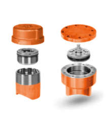
Series 150 lbs nipples are used to perform a wide range of operations from plugging with the line in service, lateral connections, extensions, purging and equalization. The fittings have a maximum working pressure of 285 psi (20 bar) at 38°C to ASME B31.8 or 245 psi (17 bar) at 82°C to ASME B31.4. Available in sizes 1.1/2″, 2″, 3″ threaded and 4″ through 12″ flanged connection. They are constructed with traceable materials and are compatible with valves and machines of international use.
2″ AND 3″ HIGH PRESSURE EQUALIZATION AND SEALING NIPPLES
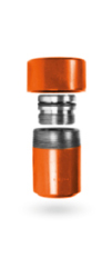
The nipples can be used as bleed and/or equalizing fittings in a variety of in-service tapping and plugging applications. They are available in two sizes, 2″ and 3″. The nipples have a maximum operating pressure of 1,500 psi (103 bar) at 82° C (82° C). The fittings come equipped with a cap, O-ring and threaded plug. They are constructed of traceable materials and are compatible with valves and machines in international use.
SEALING TEE SERIES 150 LBS
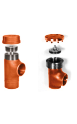
Flat bottom tees eliminate the need to install permanent valves in the connections during the making of a bypass with the line in service, either for tapping or bay-pass. Adaptation to the pipe diameter can be made in the field making them highly flexible and suitable for this purpose. The fittings have a maximum working pressure of 20 bar (285 psi) at 38 ° C according to ASME B38.1 or 17 bar (245 psi) at 82 ° C according to ASME B31.4. Available in sizes 1.1/2″, 2″, 3″ with threaded machine connection and 4″ up to 12″ with flanged connection. They are constructed with traceable materials and are compatible with valves and machines of international use.
SEALING FITTING 300LBS SERIES
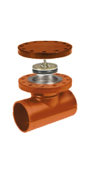
The 300Lbs split tee fittings are designed for in-service operations. This allows maintenance, repairs, plugging, etc., to be carried out without having to interrupt the supply. The fittings are extruded and have a sealing flange compatible with ANSI B 16.5 class 300, completing the set a blind flange with its studs, nuts and gasket to ensure the closure once the operation is finished. These fittings can also be built in reduction mode between the main and the branch. Maximum operating pressure of 51 bar (740 psi) at 38 ° C. Suitable for use on 2″ to 12″ lines.
300 LBS SERIES TEE AND SADDLE SEALING FITTING
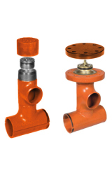
The tee sealing fittings eliminate the need to install permanent valves in the connections during the realization of bypasses with the line in service, either by bay-pass or by-passes. In 2″ and 3″ the tee is connected to the sandwich valve by means of NPT threads, and is equipped with a cap and a sealing plug with its corresponding O-ring. In 4″ to 12″ it is equipped with a sealing flange compatible with ANSI B16.5 class 300, and is provided with a sealing plug with O-ring, blind flange, studs, nuts and gasket. Maximum operating pressure of the 300D 3-WAY Tee is 49 bar (740 psi) at 38 ° C. These fittings can also be built in reducing mode between the main and the branch.
SPHERICAL SEALING TEE 300 LBS SERIES
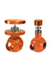
The 300D spherical tee can be used to install permanent bypasses with the pipeline in service. In 2″ and 3″ the tee is connected to the sandwich valve by means of NPT threads, and is equipped with a cap and sealing plug with corresponding O-ring. In 4″ to 12″ it is equipped with a sealing flange compatible with ANSI B16.5 class 300, and is provided with a sealing plug with O-ring, blind flange, studs, nuts and gasket. Maximum operating pressure 49 bar (740 psi) at 38 °C. Its lower part can be rotated for side or bottom bypass for ease of installation in the field. These fittings can also be built in a reducing mode between the main and the branch.
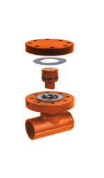
HIGH PRESSURE SEALING FITTING
The split tee high pressure sealing fittings are designed for in-service operations. This allows maintenance, repairs, sealing, etc. to be carried out without having to interrupt the supply. The fittings are equipped with sealing flanges designed to be compatible with ASME B 16.5 flanges in their 150, 300 or 600 series. Other ASME class series are available upon request, manufactured for 4″ to 24″ pipe as standard. Larger fittings are available upon request. The fittings are extruded or welded according to their size and have a sealing flange compatible with ANSI B 16.5, completing the set a blind flange with its studs, nuts and gasket to ensure the closure once the operation is finished.
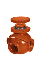
3-WAY SPHERICAL TEE WITH SEALING FLANGE
Three-way spherical tees are designed to pierce the pipeline without interrupting service, allowing bypasses to be made under service conditions. Three-way spherical tees are equipped with sealing flanges designed to be compatible with ASME B 16.5 flanges in their 150, 300 or 600 series. Other ASME class series are available upon request. The three-way spherical tees are compact and low profile, with a side outlet at the same level as the main. For standard sizes 4″ to 12″, the bottom half of the fitting can also be repositioned 180 degrees to the flange to create a bottom outlet. For sizes 16″ and larger, the fitting is made to order as a side or bottom outlet. The fittings are extruded and have an ANSI B 16.5 compliant sealing flange, complete with a blind flange with studs, nuts and gasket to secure the seal after the operation is complete.
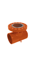
TOTAL ENCIRCLING FITTING FOR ANSI B16.5 FLANGE CAPPING
This split tee full circle fitting is manufactured from 2″ to 30″ as standard, in full bore or reducing sizes, to meet the specific requirements of various pipe plugging and tapping operations. Larger size fittings are available upon request. Fittings are extruded or welded to size and have a standard ANSI B 16.5, 150, 300 or 600 series flange with RF or RTJ shoulder.
FORGING ACCESSORIES
Futura’s plant in Gualeguaychú has the capacity to forge parts to meet the needs of third parties, designing and developing all the necessary tools, including crankshafts, connecting rods, wellheads, spheres and valve bodies, bridge crane wheels, tubular plates, and other parts for companies in the gas, oil, and mining industries.
For this task, we have independent hammer and press lines, both with their own heating furnaces, main machine, and finishing machine (deburring press).
We offer this service on our 4,000-ton press line and 16,000- and 25,000-kg hammer lines to cover parts from 6 to 480 kg.
FIGURES 8
CHARACTERISTICS AND TECHNICAL SPECIFICATIONS
FIGURES 8
It is a simple safety device that is installed between two pipe flanges. During normal operation the open end is installed to provide a spacing that allows uninterrupted flow. To stop this fluid in the pipeline, the trailing end of the blind flange must be rotated within a space between the flanges. This positively isolates the piping and equipment.
They are generally installed as a permanent device. Their geometry gives a quick visual indication of their orientation and makes it possible to see whether or not it is safe to start running fluid work.
PADDLE BLINDS
It is basically the solid half of a Spectacle Blind. It is usually made of a solid metal disc and usually has a length of metal attached to one of the end ends to be used as a handle. A finished paddle blind will resemble the shape of a paddle, hence the name. Generally these types of blind flanges are applied in piping systems that do not require constant maintenance.
They are mostly used as temporary locking devices to restrain fluids in process piping systems.
PADDLE SPACERS
Es la parte abierta del “spectacle blind”. Son a menudo hechos de un disco de metal sólido y generalmente tienen una longitud muy delgada de metal adjunta a uno de los extremos para ser utilizada como manija. Un “paddle spacer” acabado se asemejará a la forma de una paleta con una abertura en su centro. Es utilizada en lugar de los “paddle blinds” cuando el sistema de tuberías es puesto nuevamente en funcionamiento.
TECHNICAL SPECIFICATIONS
|The thickness of the blind flange line flow equipment is based on ASME B16.48 specifications and is designed to withstand any pressure and temperature combination that an ASME flange can tolerate.
|For paddle spacers, the diameter on your handle is ½” for 1″ of width, and ¾” for 1 ½” of handle width. However, this option is available if required by the customer.
|A standard shop primer coat shall be applied to all steel flanges unless otherwise specified.
|Factory finish is standard. Other surface finishes are available. Contact factory for available options.
|Standard materials are: SA5 16 GR. 70 | 304 Stainless steel | 316 Stainless steel | Other alloys can be manufactured upon request.
|Blind flange line flow equipment is produced in strict accordance with the following codes of practice: ASME B16.48 – ASME B16.5 – ASME B16.47 (for larger diameter flanges).
 Título de la pestaña 1
  Título de la pestaña 1
  Título de la pestaña 1
  Título de la pestaña 1
  Título de la pestaña 1
  Título de la pestaña 1
  Título de la pestaña 1
 HIGH PRESSURE API
HEADERS AND ARMATURES
CASING PIPE HEADS
CASING PIPE REELS
CASING HANGERS
WEAR BUSHINGS – REMOVAL TOOL
SECONDARY PACKINGS
SINGLE PRODUCTION REELS AND HANGERS
DUAL PRODUCTION REELS AND HANGERS
FLOW CONTROLLERS AND REGULATORS
FLANGES
These are elements that allow the connection or assembly of parts, whether pipes, valves, pumps, or other equipment that form part of the line or duct.
TYPES OF FLANGES
|Welding.neck
|Blind
|Ciega
|Socket Welding
|Threaded
|Lap-Joint
|Plate holder
MANUFACTURING STANDARD
|B16.5 (up to and including 24″)
|B16.47 Type A/B (26″ and above)
|B16.36 (Lap-joint)
FACE TYPES
|Flat face (FF)
|Raised face (RF)
|Ring face (RTJ)
SERIES / CLASS
150#, 300#, 600#, 900#, 1500# y 2500#
MATERIALS
|Carbon steel:
· ASTM A105
· A350 LF2 CL1
· ASTM A694 F42 /46/52/56/60/65/70
|Alloy steel:
|Stainless steel:
All our flanges are delivered with their corresponding quality certificate.
TIPOS DE BRIDAS
|Welding.neck
|Slip-on
|Ciega
|Socket Welding
|Roscada
|Lap-Joint
|Portaplaca
NORMA DE FABRICACIÓN
|B16.5 (hasta 24” inclusive)
|B16.47 Tipo A/ B (de 26” en adelante)
|B16.36 (Portaplaca)
TIPOS DE CARAS
|Cara plana (FF) flat face
|Cara con resalte (RF) raised face
|Cara con anillo (RTJ)
SERIE / CLASE
150#, 300#, 600#, 900#, 1500# y 2500#
MATERIALES
|Acero al carbono:
· ASTM A105
· A350 LF2 CL1
· ASTM A694 F42 /46/52/56/60/65/70
|Acero aleado:
|Acero Inoxidable:
Todas nuestras bridas se entregan con su certificado de calidad correspondiente.
DESCARGA DE ARCHIVOS
FLANGES
Flange is the element that joins two components of a piping system, allowing to be disassembled without destructive operations, thanks to a circumference of holes through which union bolts are mounted. The flanges are those elements of the pipeline, intended to allow the union of the parts that make up this installation, whether pipes, valves, pumps or other equipment that is part of these facilities.
The flange is an element that can be supplied as a separate part or can be factory assembled to an element for its installation, whether it is a valve or a pipe, etc. There is a diversity of designs, dimensions, materials and manufacturing standards.
TYPES OF FLANGES
The most common flange designs are:
|API 6A and 6B flanges
|Neck flanges (Welding.neck)
|Crazy flanges (lap joints)
|Socket Welding (Socket Welding)
|Threaded flanges
|Blind flanges
|Slip-on cable ties
|Long flanges – welding
|Anchor Flanges
|Double spreader flanges
|AWWA Flanges
FACE TYPES
Flange faces are manufactured as standard to maintain specific dimensions. The most common standard flange faces are:
|Flat face (FF) flat face
|Raised face (RF) raised face
|Face with ring (RTJ)
API 6A AND 6B FLANGES
API Specification 6A (ISO 10423) is the recognized standard in the petroleum industry that applies to wellheads and Christmas trees and was created to provide a safe, dimensionally and functionally interchangeable medium.
It provides detailed requirements for the manufacture of equipment for the suspension of tubulars, valves and connectors used at oil and gas well locations which contain and control the pressure and flow of fluid. It also serves as a reference source for the design of flanged connections.
ASME/ANSI FLANGES
Pipe flanges according to ASME/ANSI B16.5 or ASME/ANSI B16.47 are normally made from forgings with machined faces. They are classified according to their “pressure class” (a ratio from which a curve can be obtained according to the resistance to the joint pressure-temperature effect). Pressure classes are expressed in pounds per square inch (abbreviated as psi or simply the symbol #).
The most common pressure classes are 150#, 300#, 600#, 900#, 1500# and 2500#, although ASME B16.47 recognizes class 75# which is intended for low working pressures and temperatures.
The higher the pressure class of the flanges of a piping network, the greater the resistance of the network to the combined effect of pressure and temperature. Thus, for example, a system with a 150# class would hardly withstand pressure and temperature conditions of 30 bar and 150 °C, whereas a 300# class would be ideal for those conditions. The higher the pipe class of a flange, the higher the price, so it would be an unjustified expense to use 600# flanges for this particular case.
OTHER STANDARDS
There are also flanges under the European DIN Standard, which use the designation PN (Nominal Pressure). They are thus classified as PN6, PN10, PN16, PN25, PN40, PN40, PN100, PN250, PN400 BARS. Sometimes the letters “ND” from the German “NENNDRUCK” are still used instead of PN.
MATERIALS
The materials normally used are (according to ASME designation):
|SA-A105
|SA-A266
|SA-A182
|SA-A694
DESCARGA DE ARCHIVOS
QUICK CLOSING LIDS
The quick opening and closing lids are an indispensable device for the proper operation and maintenance of Filters, Two-phase / Three-phase Separators, Scrapers Launchers and Receivers, Boilers, etc. They present a functional, modern and economical solution for vessels under pressure, which require frequent and quick access. They can be supplied for Horizontal or Vertical position equipment. They allow a fast access thanks to their opening system by means of hinges or “clamps” that can be operated by a single person without the use of special tools.
Their main benefit is the saving of resources, both in terms of personnel and time spent in the field. That is to say, a Futura Quick Closing Lid gives to the operation of pig entry or filter cleaning, a speed and security of work really differential compared to its counterpart of disassembly and assembly that must be done in front of a blind flange.
The versatility in its varied design, which in all cases can be adjusted to the needs of the available place or the design of the equipment and its constructive capabilities, provide the user with a unique working response.
Available from 3″ upwards and for different working pressure requirements. Just fill in the Data Certification corresponding to the chosen Cover.
Futura Quick Action Caps are always supplied with a User and Installation Manual and our Technical Support to provide you with complete support.
More than 6000 units installed, both in Argentina and Latin America, with no claims of use and operation over time, endorse our product.
HORIZONTAL MODEL | SIDE OPENING
HIGH SPEED AND SIMPLICITY
A simple and very effective solution for small diameter caps. Very fast opening, its system allows it to be used in horizontal or vertical position indistinctly.

OPENING SEQUENCE

HORIZONTAL MODEL | LEVER OPENING
SPEED, SOLIDITY AND STRENGTH
We created a fast system based on the simplicity of its opening system. In a few minutes the operation is performed by one person without the use of special tools. This design is used for medium size lids.
The system of levers and hinges makes it sturdy and safe to operate. The bolts and pins of its closing system are made of stainless steel to avoid galling during opening over time.

OPENING SEQUENCE

HORIZONTAL MODEL | OPENING WITH HANDWHEEL
ROBUSTNESS AND SAFETY
This design is used on large diameter lids. Its operation is very simple, with its safety system on the front of the cover and its operating handwheel, which makes the use of additional tools unnecessary.

OPENING SEQUENCE

HORIZONTAL MODEL | RING LOCK
Our Quick-Lock Caps have 10 years of warranty and quality assured because they are calculated according to ASME VIII and validated through finite element calculations and other studies such as the measurement of deformation in the main components. In addition, we have been manufacturing covers for 20 years and they are installed in different countries: Colombia, Ecuador, Peru, Bolivia, Brazil, Uruguay, Chile and Argentina.

OPENING SEQUENCE

FILE DOWNLOADS
DATA CERTIFICATION
SHUNT FITTINGS
The Outlets type branch fittings provide countless advantages in terms of installation and final job cost. Their installation avoids unnecessary pipe cutting and welding in relation to common welding fittings.
The design of its passageway alleviates head loss and turbulence problems. Its welding system to the manifold, by means of a variable angle bevel, also allows to obtain a reinforcement in the connection area. They are manufactured in carbon, alloy and stainless steel.
Their dimensions comply with MSS SP 97 and ANSI/ASME B 36.10 standards.
SOCKINSERT | WELDINSERT THREADINSERT
These are fittings used to make 90° branches from the main pipe. They differ from each other in the method of fixing the branch. As the name suggests, they are Butt-welding, Socket-welding, and threaded (NPT) respectively.
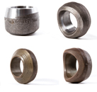
LATROINSERT
It is a fitting used to make branches at 45° with respect to the line. They can be threaded, beveled (Butt-welding), flat or with welding seat (for Socket-welding).
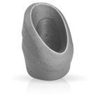
ELBOINSERT
It is a fitting for making derivations from 90° long radius elbows. Its ends can be threaded, beveled (Buttwelding), flat or with seat for welding (Socket-welding).
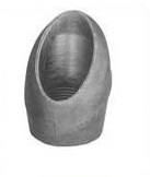
NIPOINSERT
It is a fitting used to make 90° derivations in small diameters. Its ends are male type and can be threaded, beveled, flat or with a seat for welding.

SEALING ACCESSORIES
Futura has been manufacturing fittings for over 40 years. They are designed, tested and manufactured for use on pipelines operating under the following codes: ANSI B31.8, ANSI B31.4, ANSI B31.3, DOT 192, DOT 195 and many others.
Futura fittings are designed using the area placement method for reinforcement as outlined in ANSI B31.8, B31.4 and B31.3.
Fittings are available in a variety of materials including Low CE, Crome Moly, stainless steel and others.

SEALING NIPPLES SERIES 150 LBS
Series 150 lbs nipples are used to perform a wide range of operations from plugging with the line in service, lateral connections, extensions, purging and equalization. The fittings have a maximum working pressure of 285 psi (20 bar) at 38°C to ASME B31.8 or 245 psi (17 bar) at 82°C to ASME B31.4. Available in sizes 1.1/2″, 2″, 3″ threaded and 4″ through 12″ flanged connection. They are constructed with traceable materials and are compatible with valves and machines of international use.

2″ AND 3″ HIGH PRESSURE EQUALIZATION AND SEALING NIPPLES
The nipples can be used as bleed and/or equalizing fittings in a variety of in-service tapping and plugging applications. They are available in two sizes, 2″ and 3″. The nipples have a maximum operating pressure of 1,500 psi (103 bar) at 82° C (82° C). The fittings come equipped with a cap, O-ring and threaded plug. They are constructed of traceable materials and are compatible with valves and machines in international use.

SEALING TEE SERIES 150 LBS
Flat bottom tees eliminate the need to install permanent valves in the connections during the making of a bypass with the line in service, either for tapping or bay-pass. Adaptation to the pipe diameter can be made in the field making them highly flexible and suitable for this purpose. The fittings have a maximum working pressure of 20 bar (285 psi) at 38 ° C according to ASME B38.1 or 17 bar (245 psi) at 82 ° C according to ASME B31.4. Available in sizes 1.1/2″, 2″, 3″ with threaded machine connection and 4″ up to 12″ with flanged connection. They are constructed with traceable materials and are compatible with valves and machines of international use.

SEALING FITTING 300LBS SERIES
The 300Lbs split tee fittings are designed for in-service operations. This allows maintenance, repairs, plugging, etc., to be carried out without having to interrupt the supply. The fittings are extruded and have a sealing flange compatible with ANSI B 16.5 class 300, completing the set a blind flange with its studs, nuts and gasket to ensure the closure once the operation is finished. These fittings can also be built in reduction mode between the main and the branch. Maximum operating pressure of 51 bar (740 psi) at 38 ° C. Suitable for use on 2″ to 12″ lines.

300 LBS SERIES TEE AND SADDLE SEALING FITTING
The tee sealing fittings eliminate the need to install permanent valves in the connections during the realization of bypasses with the line in service, either by bay-pass or by-passes. In 2″ and 3″ the tee is connected to the sandwich valve by means of NPT threads, and is equipped with a cap and a sealing plug with its corresponding O-ring. In 4″ to 12″ it is equipped with a sealing flange compatible with ANSI B16.5 class 300, and is provided with a sealing plug with O-ring, blind flange, studs, nuts and gasket. Maximum operating pressure of the 300D 3-WAY Tee is 49 bar (740 psi) at 38 ° C. These fittings can also be built in reducing mode between the main and the branch.

SPHERICAL SEALING TEE 300 LBS SERIES
The 300D spherical tee can be used to install permanent bypasses with the pipeline in service. In 2″ and 3″ the tee is connected to the sandwich valve by means of NPT threads, and is equipped with a cap and sealing plug with corresponding O-ring. In 4″ to 12″ it is equipped with a sealing flange compatible with ANSI B16.5 class 300, and is provided with a sealing plug with O-ring, blind flange, studs, nuts and gasket. Maximum operating pressure 49 bar (740 psi) at 38 °C. Its lower part can be rotated for side or bottom bypass for ease of installation in the field. These fittings can also be built in a reducing mode between the main and the branch.

HIGH PRESSURE SEALING FITTING
The split tee high pressure sealing fittings are designed for in-service operations. This allows maintenance, repairs, sealing, etc. to be carried out without having to interrupt the supply. The fittings are equipped with sealing flanges designed to be compatible with ASME B 16.5 flanges in their 150, 300 or 600 series. Other ASME class series are available upon request, manufactured for 4″ to 24″ pipe as standard. Larger fittings are available upon request. The fittings are extruded or welded according to their size and have a sealing flange compatible with ANSI B 16.5, completing the set a blind flange with its studs, nuts and gasket to ensure the closure once the operation is finished.

3-WAY SPHERICAL TEE WITH SEALING FLANGE
Three-way spherical tees are designed to pierce the pipeline without interrupting service, allowing bypasses to be made under service conditions. Three-way spherical tees are equipped with sealing flanges designed to be compatible with ASME B 16.5 flanges in their 150, 300 or 600 series. Other ASME class series are available upon request. The three-way spherical tees are compact and low profile, with a side outlet at the same level as the main. For standard sizes 4″ to 12″, the bottom half of the fitting can also be repositioned 180 degrees to the flange to create a bottom outlet. For sizes 16″ and larger, the fitting is made to order as a side or bottom outlet. The fittings are extruded and have an ANSI B 16.5 compliant sealing flange, complete with a blind flange with studs, nuts and gasket to secure the seal after the operation is complete.

TOTAL ENCIRCLING FITTING FOR ANSI B16.5 FLANGE CAPPING
This split tee full circle fitting is manufactured from 2″ to 30″ as standard, in full bore or reducing sizes, to meet the specific requirements of various pipe plugging and tapping operations. Larger size fittings are available upon request. Fittings are extruded or welded to size and have a standard ANSI B 16.5, 150, 300 or 600 series flange with RF or RTJ shoulder.
FORGING ACCESSORIES
Futura’s plant in Gualeguaychú has the capacity to forge parts to meet the needs of third parties, designing and developing all the necessary tools, including crankshafts, connecting rods, wellheads, spheres and valve bodies, bridge crane wheels, tubular plates, and other parts for companies in the gas, oil, and mining industries.
For this task, we have independent hammer and press lines, both with their own heating furnaces, main machine, and finishing machine (deburring press).
We offer this service on our 4,000-ton press line and 16,000- and 25,000-kg hammer lines to cover parts from 6 to 480 kg.
FIGURES 8
CHARACTERISTICS AND TECHNICAL SPECIFICATIONS
FIGURES 8
It is a simple safety device that is installed between two pipe flanges. During normal operation the open end is installed to provide a spacing that allows uninterrupted flow. To stop this fluid in the pipeline, the trailing end of the blind flange must be rotated within a space between the flanges. This positively isolates the piping and equipment.
They are generally installed as a permanent device. Their geometry gives a quick visual indication of their orientation and makes it possible to see whether or not it is safe to start running fluid work.
PADDLE BLINDS
It is basically the solid half of a Spectacle Blind. It is usually made of a solid metal disc and usually has a length of metal attached to one of the end ends to be used as a handle. A finished paddle blind will resemble the shape of a paddle, hence the name. Generally these types of blind flanges are applied in piping systems that do not require constant maintenance.
They are mostly used as temporary locking devices to restrain fluids in process piping systems.
PADDLE SPACERS
Es la parte abierta del “spectacle blind”. Son a menudo hechos de un disco de metal sólido y generalmente tienen una longitud muy delgada de metal adjunta a uno de los extremos para ser utilizada como manija. Un “paddle spacer” acabado se asemejará a la forma de una paleta con una abertura en su centro. Es utilizada en lugar de los “paddle blinds” cuando el sistema de tuberías es puesto nuevamente en funcionamiento.
TECHNICAL SPECIFICATIONS
|The thickness of the blind flange line flow equipment is based on ASME B16.48 specifications and is designed to withstand any pressure and temperature combination that an ASME flange can tolerate.
|For paddle spacers, the diameter on your handle is ½” for 1″ of width, and ¾” for 1 ½” of handle width. However, this option is available if required by the customer.
|A standard shop primer coat shall be applied to all steel flanges unless otherwise specified.
|Factory finish is standard. Other surface finishes are available. Contact factory for available options.
|Standard materials are: SA5 16 GR. 70 | 304 Stainless steel | 316 Stainless steel | Other alloys can be manufactured upon request.
|Blind flange line flow equipment is produced in strict accordance with the following codes of practice: ASME B16.48 – ASME B16.5 – ASME B16.47 (for larger diameter flanges).